| Brief pen picture of school: |
William Farr School is a rural 11-18 C of E fully comprehensive school set in the village of Welton-by-Lincoln. It has over 1500 pupils. The D&T department is a lead subject in school which has Science College, Raising Achievement, T & L and Leading Edge status.
The department has 4 full time teachers and three part time teachers, with 1 full-time Head Technician and 2 part-time Technicians. It has 2 workshops, 1 electronics lab, a CAD suite, a graphics suite, 2 food rooms, a 6th Form work room and a textiles room. At Key Stage 3 pupils have two, one hour lessons where they carousel through Electronics, Food, Graphics, Resistant Materials and Textiles. GCSE is optional and students have the choice of Systems and Control Technology with Electronics, Food Technology, Graphic Products, Resistant Materials Technology and Textiles Technology. Pupils have two, one hour lessons one week, and three the next. At A-Level students opt into Product Design (3D), Systems and Control with Electronics, Art Textiles and Art Graphic Design.
The team includes Ben Price (Head of Design and Technology), Mike Grimsley and John Clarke (Head Technician). Ben and Mike teach Electronics, Resistant Materials and Graphics up to A-Level. Ben runs the GCSE Systems & Control Electronics, A-Level Product Design and Product Design with Electronics courses. Mike currently teaches Electronics at Key Stage 3 and Graphics at GCSE. Although John heads up two other full-time technicians which work across the department in all areas, he is our main workshop technician for RM and Electronics.
Last year’s results in GCSE Systems and Control with Electronics gained 86% A*-C (50% A*-A) one of which gained one of the top five highest Electronics results in the country. |
Commentary:
Circuit Commentary
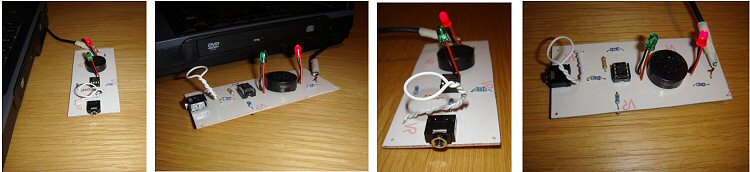
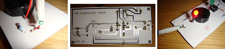
I used Circuit Wizard to draw out the circuit diagram for an 8-pin PIC (GENIE-C08), however I will have to use an 18-pin PIC (DAISY-18) and a Darlington Driver, on the surface mount boards in order to drive the speaker, as a DAISY-08 doesn’t have enough power to drive an output like a speaker. The boards shown are for a Year 9 Homework Timer and will build on children’s previous knowledge and understanding on PICs from Year 8.
I did have to experiment with power. Currently powering Transistor and 555 projects in Key Stage 3, means using a PP3 9 volt battery. Powering PICs needs 4.5 - 6 volts, which when using a 9v battery snap indicates the use of a PP3 which will blow the PIC, so we use cell batteries. These are smaller, but quite expensive compared to PP3s which are also more readily available.
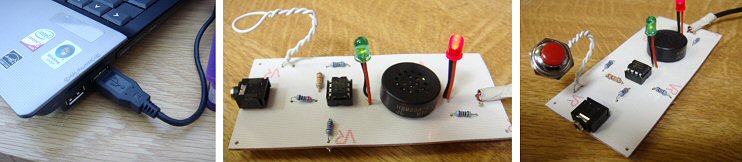
As a lot of homework these days is completed on the computer, 4.5 volts can be gained from a USB connection, so it can be plugged into a USB port and can time doing homework, without the use of batteries. It can also be used for playing on the computer or games consoles as a lot of these have USB ports. As well as being powered by a USB, I want it to be downloaded to, via a download socket, something I haven’t used on pupil’s PCBs before due to time, cost and complication.
After drawing the circuit diagram, I moved on to drawing the PCB. I wanted the power to be connected from the back of the device, with the download socket to be placed at the front, easy access for changing the timing period, and no confusion. As the device will sit on top of the PC tower, PC flat bed or console, I wanted it to be low profile and long and thin.
When I had finished designing the PCB, and John telling me that it had to be so many millimetres smaller in height and width in order to fit multiples on our boards, I moved on to the Flowchart. The flowchart function on Circuit Wizard works really well as it links with the Circuit Diagram and PCB Diagram. The program can run on the flowchart screen, as well as the Circuit Diagram and PCB Diagram screen.
Once the PTM (G3) is pressed, the Blue LED (G4) will go high, causing it to come on. The loudspeaker (G2) will then beep several times to indicate the starting of the time period, by going high, wait, low etc. It will then count for 30 minutes (standard KS3 homework time) which is 1800 seconds with a high LED (G4). After this time it will flash G4 high (LED) and play a tune via G2 (speaker).
The PCB can be connected to the laptop/PC via a download socket and can be tested on screen which can help you to fault find the circuit.
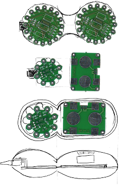
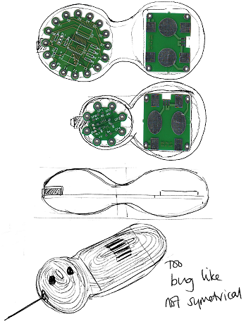
In order to transfer this circuit to surface mount board technology, I had to spread the circuit over two boards with flying leads and mini boards with components on. This had to be done via sketches as it would be complicated on Circuit Wizard.
Developmental Work Undertaken At School (Casing)
The PCB soldered together quite easily and the trickiest part was the USB lead that I was able to get hold of from the ICT Technician. This will have to be sourced quite cheaply if this project is going to run with 240 pupils. Can every Year 9 child bring in a USB lead?
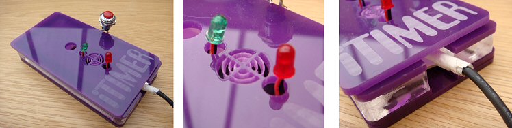
The PCB worked well, and then I turned my attention to the casing. Now I knew the PCB worked, I could use the measurements to design my casing. From my initial design sketches I knew which one I was going to make on the 3D printer and which one I was I was going to make in school. Having a Laser Cutter allows me to cut cases quickly and easily, making the casing a quick assembly rather than a drawn out task over several lessons. With an idea in mind, I had to choose how I was going to make my enclosure; layered 3mm acrylic, vacuum formed HIPS with a spigotted acrylic base, strip heated acrylic walls with acrylic lid and base or buy an ABS box from Rapid.
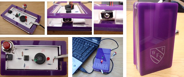
I initially used the layered acrylic box but it uses a lot of acrylic (see photo), and thought about making an acrylic carcass with panels, a lid and a base, like our Year 8 project, but that would be revisiting the same way of making cases. I didn’t want to have to buy in 240 ABS cases from Rapid as I didn’t think that they would look particularly stylish. Technology Supplies do a former for the case and base which could be a solution, as opposed to using an acrylic (or MDF base).
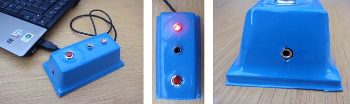
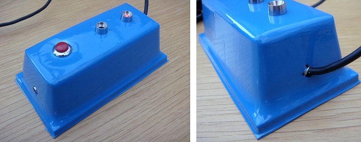
I decided to go with the vacuum forming method and make my own former. I than asked John to make 6 copies so that we can knock out 6 at a time when vac forming from a sheet of HIPs. The HIPs casing idea locks and locates over a piece of 3mm acrylic which acts as a spigot. There the PCB can be attached to the base with some PCB legs which can be glue gunned onto the inside of the base. This will allow the board to line up holes in the casing for download jack to line up with the download socket. The enclosure will have to be made from 1.5mm or 2mm HIPs. A hole will be drilled in one end to allow the USB to be fed through before being soldered, and a hole drilled in the other end, big enough for the download socket to fit through.
Back at School
By the time I came to trial this product, we were already into the final rotation of the year, so I decided to work with my Year 10 Systems pupils. As we had started coursework, it was too late to build it into a project for them, so they stayed behind after school and worked in their own time with some bribery of chocolates and sweets. I then ironed out any problems they had in the remainder of the summer term and planned to run this through with Year 9 groups from September 2009 onwards.
PCBs were designed by myself and made by John. I talked through ideas with Mike and we all helped to staff the after school sessions with my Year 10s.
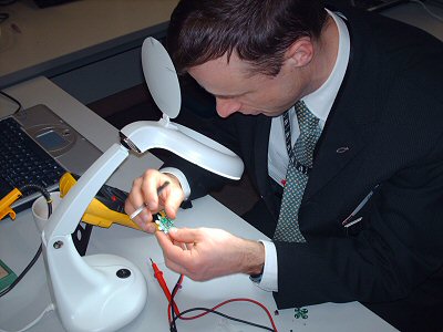
Soldering only took 2 hours after school as they had become more experienced during their year in Year 10, making two projects and completing a PIC workshop I ran in the summer term.
The programming didn’t take long as I had already saved the file on the network for the pupils to download with a USB download cable. I had previously bought 14 serial cables for PIC Logicator, that was connected to my 14 PCs. These worked fine with Circuit Wizard and the GENIE-C08 and DAISY-08.
We also discussed along the way, other uses for the timer which included egg timers, sunbathing timers, a timer to time running a distance, bleep test, homework, playing on your computer and brushing your teeth, which was the old Year 8 project, before the old Year 9 project was moved back into Year 8.
Casing was drilled and popped together nicely. Some bezelled LED holders were used to improve the aesthetic quality of the product and 14 happy Year 10s went home with their products, eager to try them out.
The one problem that came back from the group, was that it wasn’t loud enough. This would need an amplifier, either a NPN Transistor, Darlington Pair, or a ULN Darlington Driver IC. This would result in more soldering, therefore it would take longer to make, be more expensive and be a larger board, especially if using a Darlington Pair or Darlington Driver. |