Carre's Grammar School Carre's Grammar School
|
| School Postcode: NG34 7DD |
DCFS number: |
| Staff member who developed this case study: |
Ashley Thomas |
| Email contact: |
ashley.thomas@carres.lincs.sch.uk |
| School telephone: 01529 302181 |
No. on roll: 704 |
| Brief pen picture of school: |
4 full time members consisting of 3 teachers and 1 technician, with 1 part time member of staff. The school offers Resistant Materials and Electronic Products at GCSE. |
1. The Teacher CPD Course: |
The Project Brief:
I am going to design and make a product that gives out 3 different sounds depending on which of the 3 Ibutton’s is inserted into the product. The product should take the form of a musical note of some description and must be produced using techniques that could lend itself to batch and mass production. |
| Specification:
Production Techniques.
The casing of the product should be produced either by a 3D printer or a laser cutter. The circuit should be produced using Circuit Wizard BETA to produce a PCB mask and subsequently chemical etching it.
Function.
The circuit must use Genie chips, with the musical Genie chips employing RTTTL files for the sound. The sound from the circuit may use a piezo electrical actuator or a buzzer.
Form.
The product must take the form of a musical instrument that is both rugged and aesthetically pleasing. The circuit must be encased in a custom made case.
User.
The user must be able to pass the product around a classroom so durability is a key aspect of this product. The casing must give access to a battery pack so that the product does not have to be opened up to change the power supply. |
| Concept Sketches: |
| 1. Electronic circuit development: |
a) Circuit diagrams/schematics
|
b) PCB artwork
|
c) Program details |
| The Final Circuit Board:
|
|
| Commentary: |
| 2. CAD/CAM Development: |
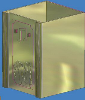
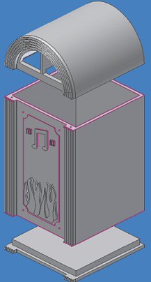
| Final CAD Design:
These are two designs that I decided to carry forward and model in Autodesk Inventor.
The Jukebox design was not feasible as it was too large and not rugged enough for a classroom environment. Plus I thought that the whole design lacked the organic feel I was looking for.
This first radio design gave me a more organic feel I was looking for. However it was decided that the musical notes would be too thin and delicate to be machined by a CNC lighter, so I decided to laser cut them and adds them to the design later.
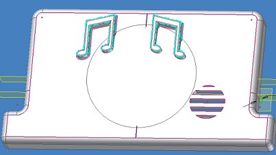
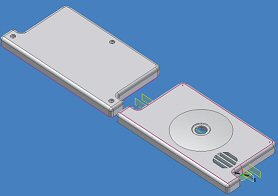
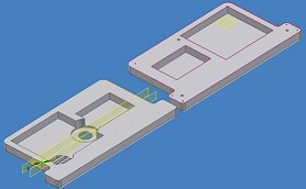
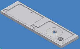
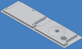
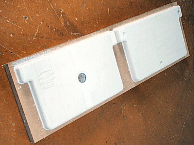
Final Machining of the casing for the product.
These screen grabs show that the final casing. One the top view (below left) then the musical notes are missing this is because I produced them using Corel Draw and a laser cutter. The underside view (bottom right) you will see that the cuts out will house the circuits and the battery holder.
The screen grabs below show that the design is inset and outset of the material so that I could machine the outside and inside of the material.
|
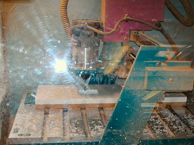
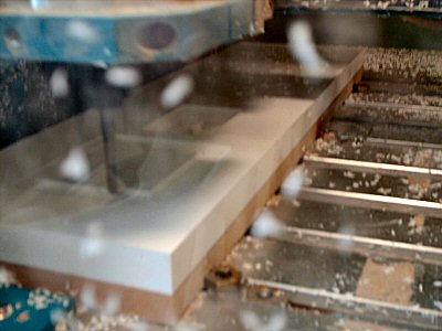
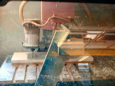
CAM Manufacture:
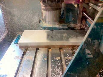
This is a picture of the CNC cutter in operation. The cutter is cutting out the inside billet.
|
 |
|
Commentary:
Problems with the circuit.
After finishing the circuit and the casing I decided to test the product. The outcome was not as expected, When 1st 'i-button" was touched on, it played the tune at the correct volume, at the end of that tune, I used the same one again and it played the correct volume; if I used a different "i-button" it only played the 1st note at the correct volume and then plays the rest of the tune quietly. If I used the reset it was fine until the second button was used. When I used the third button and it was even quieter.
Troubleshooting.
To solve this problem I decided to breadboard it, thinking it must be a hardware problem - same happened. I went back to the software made some changes and the same happened. So after lots of testing and trialling I found out it was a problem about running the same piezo from three PIC inputs. I tried all sorts of things like buffering the piezo, it did make a bit of difference, but nothing significant.
So I put an oscilloscope onto pin2, I was expecting to see a true square wave, but I was getting an AC half wave form (which I cannot explain). So I put an MPA13 high gain transistor on the output of each 08M and put the collector of each to the piezo which has made it work!
|
2. The Student Scheme of Work |
| Aimed at Key Stage: |
| Estimated time available for project: 13 periods of 60 minutes |
| National Curriculum PoS covered by Scheme of work: |
The Scheme of Work:
| Lesson |
Content Covered |
Activity |
Resources Needed |
POS |
| 1 |
Product Analysis, system recognition and Research |
Starter: - Explain to the group what is going to be covered over the module, PIC chip theory, programming techniques, different types of plastics, recap of circuit theory and soldering.
Main Activity: - Using the existing products and the worksheets get the students to analyse the products. Relate back to what the inputs, the processes and the outputs are. Labour the point that this is a system.
Presentation: - Using the presentation, highlight how Electronics has developed over the period from the cathode ray tube to the modern day Microprocessor using the presentation in the resources folder.
Main Activity 2: -Tell the group to fill in the components page in the booklet using the text books and internet.
Resource: http://www.kitronik.co.uk/data_sht.htm |
Various Products, Booklet Collins CDT Foundation Course, Textbooks, Internet |
1.1(d), 1.4(a), 3(p), 3(q), 4(a), 4(c), 3(o) |
| 2 |
PIC chips and PIC Logicator. Responding to a design brief. |
Starter: - Introduce PIC logicator; labour the point that it is an example of flow charting programming.
Demonstration: - Introduce the EISS integrating Electronics with CAD/CAM, highlight the fact that programming and pic chips can create unique products, that can potentially fulfil a variety of needs.
Main Activity: - Students are using PIC logicator to work through the activity in the work book. Students are then asked to construct a program that satisfies the design brief in the booklet. |
PIC Logicator, Booklets |
2(b), 2(c), 2 (g), 3(n), 3(o), 3(q) |
| 3 |
PIC chips and PIC Logicator |
Starter: - Recap of PIC Logicator, key errors to watch out for, (the correct chip is selected, the correct outputs are highlighted, the amount of inputs and outputs are correct).
Main Activity: - Students are continuing with the programming in PIC Sims (in their booklet) and the program for the tired eyes timer. Students are to save the finished program and then print them out and stick them in their booklets ready to annotate them. |
PIC Logicator, Booklets. |
2(b), 2(c), 2 (g), 3(n), 3(o), 3(q) |
| 4 |
Circuit Wizard and pin out diagrams introduced. |
Starter: - How do we produce PCB’s? Introduction to Circuit wizard and the advantages of it, demonstrate key features.
Main activity: - Students are introduced to producing circuit drawings and PCB drawings. The students then have to generate a circuit diagram and PCB mask using Circuit Wizard. Students are to use the booklet to help them (various standard components, values, etc). Watch out for crossing copper tracks. |
Circuit Wizard, Booklets, Printer |
2(e), 2(g), 3(n), 4(f) |
| 5 |
Circuit and PCB designing |
Starter: -Students are carrying on with the production of the circuit diagrams and PCB artwork using the booklets and circuit wizard. The groups are to print them out and stick them in their booklet to annotate them.
Demonstration: -Demonstrate how to produce a PCB from the artwork using the chemical etching machine. |
Circuit Wizard, Booklets, Printer |
|
| 6 |
Designing. |
Starter: - Introduce the group to the design section and demonstrate isometric style of drawing.
Main Activity: - The group are to come up with 3 designs in the booklet making sure they are aware of the material and production methods they will be working with. (Refer to workbook). The group are to also begin designing vinyl stickers using Techsoft 2D design V2, ready for use with the vinyl cutter later on.
Demonstration: - Recap of 2D Design V2 and how it can be used in conjunction with the vinyl cutter.
Main Activity 2: - The group are to design stickers using 2D design V2 taking into account the constraints of the vinyl cutter. |
|
1.1(b), 2(a), 2(g), 4(c) |
| 7 |
Manufacture |
Starter: - Recap soldering; hazards, precautions that need to be taken. Issue the circuit boards to the group. Recap use of the line bender and what shape the timer must be, to accommodate for the circuit board and the different types of monitors.
Main Activity: -Group on task with the soldering, coming to the front for the various components.
Demonstration: -Then show the students the use of a jig and the pillar drill for drilling the acrylic. Students can then begin to drill their pieces of acrylic. |
Soldering Boards, Aprons, Soldering Iron, Solder, Booklets, Jig, Pillar Drill |
3(j), 3(L), 3(m) |
| 8 |
Manufacture |
Starter: -Introduce the group to the two different types of plastics and the production processes that are associated with the material.
Main Activity: - Students soldering/ drilling/ line bending/ and coming to the front to for a PIC chip to test and download a program. |
Presentation of thermo set and thermo plastics, Line bending machine, Pieces of acrylic for the main structure. |
3(j), 3(k), 3(L), 3(m) |
| 9 |
Manufacture |
Starter: - Groups told this is the last lesson on practical
Main Activity: - Students are finishing off the manufacture. Finishing the soldering, program upload, 2D design sticker designs and line bending.
Homework: - Revise for the test. |
Line Bender, Soldering Boards, Aprons, Soldering Irons, Solder, Booklets |
3(j), 3(L), 3(m) |
| 10 |
End of Module Test |
Starter: - Run through the whole booklet. Taking any questions as they come.
Main Activity: - Allow 10 minutes for the main test. Then go through with the group the answers and get them to report back the marks for marking down.
Get the students to start the evaluation pages of the booklet, and get the students to finish it for homework. |
Test |
2(h) |
| 11 |
CAD Development |
Starter activity: - Get the group to produce a concept CAD drawing of their product.
Main activity: - Go through step by step with the group of how to produce a CAD image. (Extension: - Gifted and Talented Students can carry on and try to complete it on their own.) |
Pro Desktop V8 |
4(f) |
| 12 |
CAD working drawing |
Starter: - Introduce working drawings and how they help in manufacturing.
Main Activity: - Ask the group to produce a working drawing of the tired eyes timer they made, using a 3rd Angle Orthographic view. |
2D design |
4(f) |
| 13 |
Programming Methods |
Starter Activity: Introduce the whole group to the task of the robot challenge. Introduce what pins the motors and outputs are on, (by referring to a buggy with the labels on)
Main Activity: - Get the students to generate a range of programs that will enable the buggy to get from one end of the course to another. |
PIC Logicator, PIC Buggy’s |
2(b), 2(c), 2(g), 3(n), 3(o), 3(q) |
|
| List the design decisions you will be asking pupils to make. Conceptual: - All students will make a tired eyes timer for their computers at home that will be powered by a USB lead that will deliver 5V.
Aesthetic: -
How will you best utilise the vinyl cutter to get a high quality unique outcome?
How will you design your structure out of plastic for your individual monitors at home (flat screen, laptops, standard monitors)?
Marketing: -
This product is aimed at you (the students), and promotes safety awareness when working on a computer.
Technical: -
The tired eyes timer is PIC programmed using PIC Logicator 6.5. The power comes from a USB lead that comes from a computer, making this a light weight portable device.
Inputs: -
Power supply comes from the USB lead. As soon as the circuit has power the program begins to take effect.
Process: - PICAXE 08 PIC chip. This allied with the programming from PIC Logicator (outputs, procedures, wait time) will make for a unique product.
Outputs: - There will be 1 red, 1 amber and 1 green LED. To tell the user when they could do with a rest from the computer.
Constructional: -
The frame of the product will be made out of acrylic. You can line bend this into any desired shape you like. This could hook over a monitor screen to be constantly visible or it could be free standing.
|
|
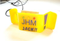
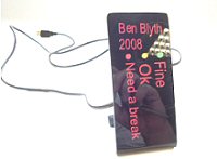
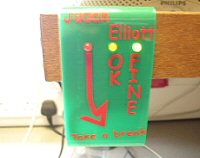
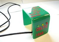
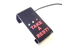
Student Outcomes:
Here are some of the outcomes of the Year 8 Tired timer project. The group managed to integrate traditional finishing techniques, programming, soldering skills and CAD/CAM to produce a functional electronic product.
The group responded well to the fact that all of them were going to produce a Tired Eyes Timer that had the same function, but could be any form they wanted.
Student Comments: I asked students to comment on the tired eyes timer project. The feedback was very pleasing:
George, “The most challenging part of the project was the programming on the computer. The part of the project I enjoyed was the sticker making using the Roland sticker cutter”
Mathew, “I enjoyed the tired eyes timer project because it was challenging. The most difficult bits were when we had to program to PIC. The bit that I enjoyed the most was drawing the designs and also producing the vinyl stickers.
Jack, “I found the stickers easy to make and fun to design after being told how to use the tools in 2D design. I was pleased with the outcome of my product because it was how I wanted it to be.
Joshua, “The challenges in this project for me were the circuit designing because it was hard to do flashing sequences and procedures. I overcame this by working a lot more independently and started to figure things out for myself.”
Judah, “I really enjoyed doing this project, we were helped a lot and we all completed it. All of the projects looked really good.”
Patrick, “I found the project challenging in a fun way and I loved doing it. The end product was fantastic and it is really useful at home. All the class did well and I hope we do something similar in the future.” |
Commentary:
The product I have asked my students to make uses a PIC chip and is programmed using PIC Logicator. The main casing is an acrylic stand that they can bend into a desired shape to fit their need. The EISS product comes in to demonstrate what can be achieved with a PIC chip and other input and output devices.
Evaluation of SOW.
Overview
So far the group have responded well to the project as a whole and find the thought of making an electronic product that is powered by a USB lead very exciting. There was no opportunity to upload students design work as they have not had chance to render and annotate their work; which was a shame as the group are on their way to producing some high quality work.
CAD/CAM integration.
The involvement of CAD comes from the designing of the circuit diagram and the PCB artwork on Circuit Wizard and from the designing of the stickers on Techsoft 2D design V2. The integration of CAM came in with the use of the vinyl cutter/plotter.
To enhance the learning of Techsoft 2D design V2 and to get a higher quality product it would be advisable to use a laser cutter. The beauty of this project and SOW is that it is future proofed if we get a laser cutter, all we need do is replace the vinyl stickers with rastered images on a piece of acrylic and the rest of the SOW would run according to plan. The advantage of using a laser cutter would be that more intricate images in the form of Jpegs could be used for decoration, and potentially grab student’s interest even more.
Professional Development.
This project has given me the chance to place myself outside of my comfort zone in terms of my Electronics understanding, this has subsequently helped me gain experience and develop my own confidence in my subject area. This project has also given me a different perspective of how CAD/CAM can be used to produce purpose built, high quality packaging for electronic products, and steer away from vacuum form moulds.
|